Description
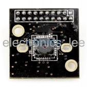
MT9D112 – 2.0 MP Camera Module w/ Stock Lens:
This product has been discontinued.
The MT9D112 – 2.0 MP Camera Module w/ Stock Lens (B0006) features the MT9D112 color sensor from Micron/Aptina. The sensor has a 1/4.0″ optical format, which combined with the pixel size of 2.2 µm x 2.2 µm, provides the 2.0 MP (1600 x 1200) UXGA image. This is a rolling shutter sensor, which captures an entire column (or row) simultaneously, and compiles the image by scanning across (or down).
Lens Mounts:
This adapter board does not offer a standard (M12 or CS) lens mount, but uses the “stock lens” attached to the sensor. In addition, camera modules with similar sensors are available from ArduCAM. For example, see the MT9D111 – 2.0 MP Camera Module for a similar (but 1/3.2″ optical format) module bundled with either an LS-2718CS lens option (B0009) or a LS-6020 (IR or NoIR) M12 lens option (B0010), as well as M12 and CS mounts only, and any compatible lens sold separately. Also, see the MT9D111 – 2.0 MP Camera Sensor w/ Autofocus Stock Lens on Adapter Board (B0054) for an autofocus option.
The key benefit of the standard lens mounts available with this module is the simplicity in swapping the lens – fisheye, wide-angle, telephoto, zoom, IR or NoIR filter – all of which are available here – click on the Camera Lenses product category for the complete selection of ArduCAM lenses. Be sure to note the compatible lens mount height (7 mm, 10 mm, etc.) for each lens selected. Each lens purchased separately comes with an appropriate height lens mount (plastic for M12, metal for CS). Click on the Camera Lens Mounts product category for information about lens mounts, including compatibility with the various lenses.
Camera Shields:
In the Arduino world, a “shield” is a piggy-back circuit board that provides additional functionality to the development board. In this context, a camera shield provides the required interface from the camera module to your computer. You may choose to create your own custom-built hardware interface via the 20-pin 0.1″ pitch connector. Or, you may purchase one of the available ArduCAM camera shields.
You may use the ArduCAM F Shield Rev V2 or the ArduCAM LF Shield Rev V2 to connect to Arduino system boards. Open-source software and binaries are provided on the ArduCAM GitHub site (see link below) for these shields.
Features:
- Sensor: MT9D112 color (Micron/Aptina)
- Full Resolution: 2.0 MP (1600 H x 1200 V)
- Optical Format: 1/4.0″
- Sensor Size: 3.56 mm x 2.68 mm
- Pixel Size: 2.2 µm x 2.2 µm
- Max Frame Rate: 15 fps at full resolution; 24 fps in preview mode; 30 fps in video mode
- Connectors: 20-pin 2.54 mm (0.1″) header
- Mount Pitch: N/A
- Board Size: ~30 mm x ~30 mm
Pinouts:
Table 1: 20-pin header interface
| Pin No. | PIN NAME | TYPE | DESCRIPTION |
| 1 | VCC | Power | 3.3 v Power Supply |
| 2 | GND | Ground | Power ground |
| 3 | SCL | Input | Two-Wire Serial Interface Clock |
| 4 | SDA | Input/Output | Two-Wire Serial Interface Data I/O |
| 5 | VSYNC | Input | Active High: Frame Valid; indicates active frame |
| 6 | HSYNC | Input | Active High: Line/Data Valid; indicates active pixels |
| 7 | PCLK | Input | Pixel Clock output from sensor |
| 8 | XCLK | Output | Master Clock into sensor |
| 9 | DOUT7 | Input | Pixel Data Output 7 |
| 10 | DOUT6 | Input | Pixel Data Output 6 |
| 11 | DOUT5 | Input | Pixel Data Output 5 |
| 12 | DOUT4 | Input | Pixel Data Output 4 |
| 13 | DOUT3 | Input | Pixel Data Output 3 |
| 14 | DOUT2 | Input | Pixel Data Output 2 |
| 15 | DOUT1 | Input | Pixel Data Output 1 |
| 16 | DOUT0 | Input | Pixel Data Output 0 (LSB) |
| 17 | NC0 | Not Connected | N/C |
| 18 | NC1 | Not Connected | N/C |
| 19 | NC2 | Not Connected | N/C |
| 20 | NC3 | Not Connected | N/C |
Package Includes:
- MT9D112 – 2.0 MP Camera Module w/ Stock Lens (qty 1)
Notes:
- The lens and/or sensor have an IR-cut filter, so this module is not suitable for IR photography.

Reviews
There are no reviews yet.