Description
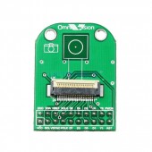
OmniVision SCCB Camera Adapter Board:
The OmniVision SCCB Camera Adapter Board (B0012) hosts most of the compatible SCCB Camera Sensors from OmniVision. The benefit of the adapter board is the lower cost of trying different sensors. Rather than buying several camera boards, simply replace one sensor with another on the adapter board.
Lens Mounts:
The sensors compatible with this adapter board are sold with a “stock” lens. So, it is not possible to use an M12 or CS lens with this product.
Camera Shields:
In the Arduino world, a “shield” is a piggy-back circuit board that provides additional functionality to the development board. In this context, a camera shield provides the required interface from the camera module to your computer. You may choose to create your own custom-built hardware interface via the 20-pin 0.1″ pitch connector. Or, you may purchase one of the available ArduCAM camera shields.
The ArduCAM USB Camera Shields USB2 Rev D (B0095) or USB3 Rev C (B0111) and Parallel Adapter Board (B0126) provide you a USB connection to a Windows, x86 Linux, Nvidia Jetson, or Raspberry Pi computer for these camera modules. You may use the ArduCAM F Shield Rev V2 (B0051) or the ArduCAM LF Shield Rev V2 (B0052) to connect to Arduino system boards. Open-source software and binaries are provided on the ArduCAM GitHub site (see link below) for these shields.
Features:
- Supports most OmniVision CMOS serial camera control bus (SCCB) camera modules.
- Single power supply range: 2.8 V ~ 3.3 V
- 8 bit RGB/YUV/Raw camera data bus
- Pin pitch: 0.1 in / 2.54 mm (20 pins)
Table 1: Partial List of Supported Camera Modules
| Resolution | Sensor Vendor | SCCB Camera Sensor |
| 0.3MP | OmniVision | OV7670 / OV7725 |
| 1.3MP | OmniVision | OV9650 |
| 2MP | OmniVision | OV2640 |
| 3MP | OmniVision | OV3640 |
| 5MP | OmniVision | OV5642 |
Pinouts:
Table 2: 20-pin header interface
| Pin No. | PIN NAME | TYPE | DESCRIPTION |
| 1 | VCC | Power | 3.3 v Power Supply |
| 2 | GND | Ground | Power ground |
| 3 | SCL | Input | Two-Wire Serial Interface Clock |
| 4 | SDA | Input/Output | Two-Wire Serial Interface Data I/O |
| 5 | VSYNC | Input | Active High: Frame Valid; indicates active frame |
| 6 | HSYNC | Input | Active High: Line/Data Valid; indicates active pixels |
| 7 | PCLK | Input | Pixel Clock output from sensor |
| 8 | XCLK | Output | Master Clock into sensor |
| 9 | DOUT7 | Input | Pixel Data Output 7 |
| 10 | DOUT6 | Input | Pixel Data Output 6 |
| 11 | DOUT5 | Input | Pixel Data Output 5 |
| 12 | DOUT4 | Input | Pixel Data Output 4 |
| 13 | DOUT3 | Input | Pixel Data Output 3 |
| 14 | DOUT2 | Input | Pixel Data Output 2 |
| 15 | DOUT1 | Input | Pixel Data Output 1 |
| 16 | DOUT0 | Input | Pixel Data Output 0 (LSB) |
| 17 | Y1 | Input | Pixel Data Output 1 in YUV 10-bit mode |
| 18 | Y2 | Input | Pixel Data Output 0 in YUV 10-bit mode |
| 19 | Flash | Output | Optional flash signal |
| 20 | PDWN | Input | Standby Mode Enable Pin; active HIGH |
| 21 | NC1 | Not Connected | N/C |
| 22 | NC0 | Not Connected | N/C |
Package Includes:
- SCCB Camera Adapter Board (qty 1)
- Note: Camera sensor is not included
Additional Resources:
- Online Documentation for ArduCAM SPI Cameras for Arduino
- ArduCAM GitHub Open Source Software for Arduino Compatible Breakout Boards
- User’s Guide – ArduCAM USB Camera Shield
- Online Documentation for ArduCAM Breakout Boards
- ArduCAM GitHub Open Source Software for ArduCAM USB Camera Shields

Reviews
There are no reviews yet.